Compression testing machines give inconsistent force readings during routine quality control, creating hidden risks for packaging reliability. To run the compression test smoothly and efficiently, the IS 1828-1:2005 standard must be followed, as it helps lab managers fix force errors early and keep crush test data accurate.
If you run quality checks in a packaging facility, inaccurate test readings can be a major problem. To test the corrugated box, place it at the bottom platen, press start, and wait for the display to show peak force. If your load cell drifts or your frame is misaligned, these numbers are baseless. A carton may look strong during the test, then buckle under normal stacking weight during transportation or shipping.
Quality teams spend a lot of time tweaking the GSM value of paper or changing glue formulas to stop box failure. However, operators often ignore that the force sensor on the machine itself reads weight incorrectly. In this article, we will look at what IS 1828-1:2005 covers, how calibration steps work out in the field, and why checking your frame setup keeps your packaging lines safe.
What is IS 1828-1:2005?
IS 1828-1:2005 defines the standard calibration and verification methods for static uniaxial testing machines in India. It gives laboratories a set of strict rules to verify force indicators across different accuracy classes.
In simple terms, the guidelines under IS 1828-1:2005 tell how to check if your testing equipment applies and displays the exact physical force. It covers both tension systems and compression rigs across industrial plants. Part 1 focuses on verifying the load indicator setup and force measurement systems inside the frame.
The standard assigns accuracy grades to test equipment, for example, Class 0.5, Class 1, etc., depending on the results of the tests. When a service engineer visits you to check the accuracy of your lab frame, they will perform these actions to check the indicator accuracy, load cell output and structural strength under heavy load.
Purpose and Scope of IS 1828-1:2005 for Compression Testing
The main intent of IS 1828-1:2005 is to establish a common set of compression frame calibration steps that measure force within a specified tolerance. It includes force indicators, load cell linearity, platen parallelism, and zero-point drift.
Any testing done on an unverified piece of machinery gives a false sense of security. When you order a shipping carton, you obviously expect a high-quality packaging box that is able to meet your requirements. The high-quality packaging items mean that they can withstand regular compression forces that are mainly exerted due to the stacking of boxes.
This is what is outlined under the IS 1828-1:2005. The standard details static load verification using certified proving rings or master load cells. It sets explicit rules for relative error, machine repeatability, and zero setting accuracy. When you run a box compression machine through dozens of crush tests daily, following these rules stops mechanical wear from ruining your historical test logs.
IS 1828-1:2005 PDF Download
If you need deeper technical details on polymer testing methods, accessing the IS 1828-1:2005 PDF gives you complete documentation to align specimen prep steps with your IS 1828-1:2005 verification requirements.
IS 1828-1:2005 Procedure for Compression Testing Machines
IS 1828-1:2005 outlines a clear guideline for the exact procedure for the calibration and verification of a static force-measuring system for a uniaxial testing machine. The test is highly recommended when you need to ensure your compression and tensile testing machines are working efficiently and accurately as they are intended to.
Test Preparation
The verification process under IS 1828-1:2005 requires visual inspection, applying test loads with master instruments, and calculating force error percentages across multiple load points. These steps verify that digital readouts match true physical forces applied to a test specimen.
Required Force Exerted
Before touching controls or running test loads, the technician inspects physical hardware. Platens must be smooth, clean, flat, and parallel. Any play in drive screws or hydraulic rams gets fixed right away because loose mechanical joints ruin initial load curves instantly.
Careful Calibration of Testing Machine
Calibration for accuracy starts once physical checks pass. A certified reference load cell sits centrally on the lower platen. The operator applies force step by step across the operating capacity, usually at 20%, 40%, 60%, 80%, and 100%. They run this sequence three times to measure repeatability.
Test Results Recorded & Evaluated
This part matters during daily lab operations. Engineers record the relative percentage error and the repeatability error at each load step. If readings stay within Class 1 limits, the machine gets an official calibration certificate. When you crush corrugated boxes on a box compression machine, these verified load points prove your peak values reflect true box strength rather than sensor drift.
After the test, based on the maximum value of relative errors like accuracy and reliability, the testing machines are classified into different classes: class 0.4, class 1, class 2, or class 3. Each class machine’s errors are determined by four major calibrated errors including relative accuracy error, relative repeatability error, relative zero error, and relative reversibility error, as follows:
|
Machine Class |
Accuracy Error (q) |
Repeatability Error (b) |
Reversibility Error (v) |
Zero Error (f?) |
|
Class 0.5 |
±0.5% |
0.5% |
±0.75% |
±0.05% |
|
Class 1 |
±1.0% |
1.0% |
±1.5% |
±0.1% |
|
Class 2 |
±2.0% |
2.0% |
±3.0% |
±0.2% |
|
Class 3 |
±3.0% |
3.0% |
±4.5% |
±0.3% |
If a machine satisfies Class 1 limits for accuracy, repeatability, and zero error but its reversibility error falls into Class 2, the entire machine is classified as Class 2. This formula works for all machines and calibrated values.
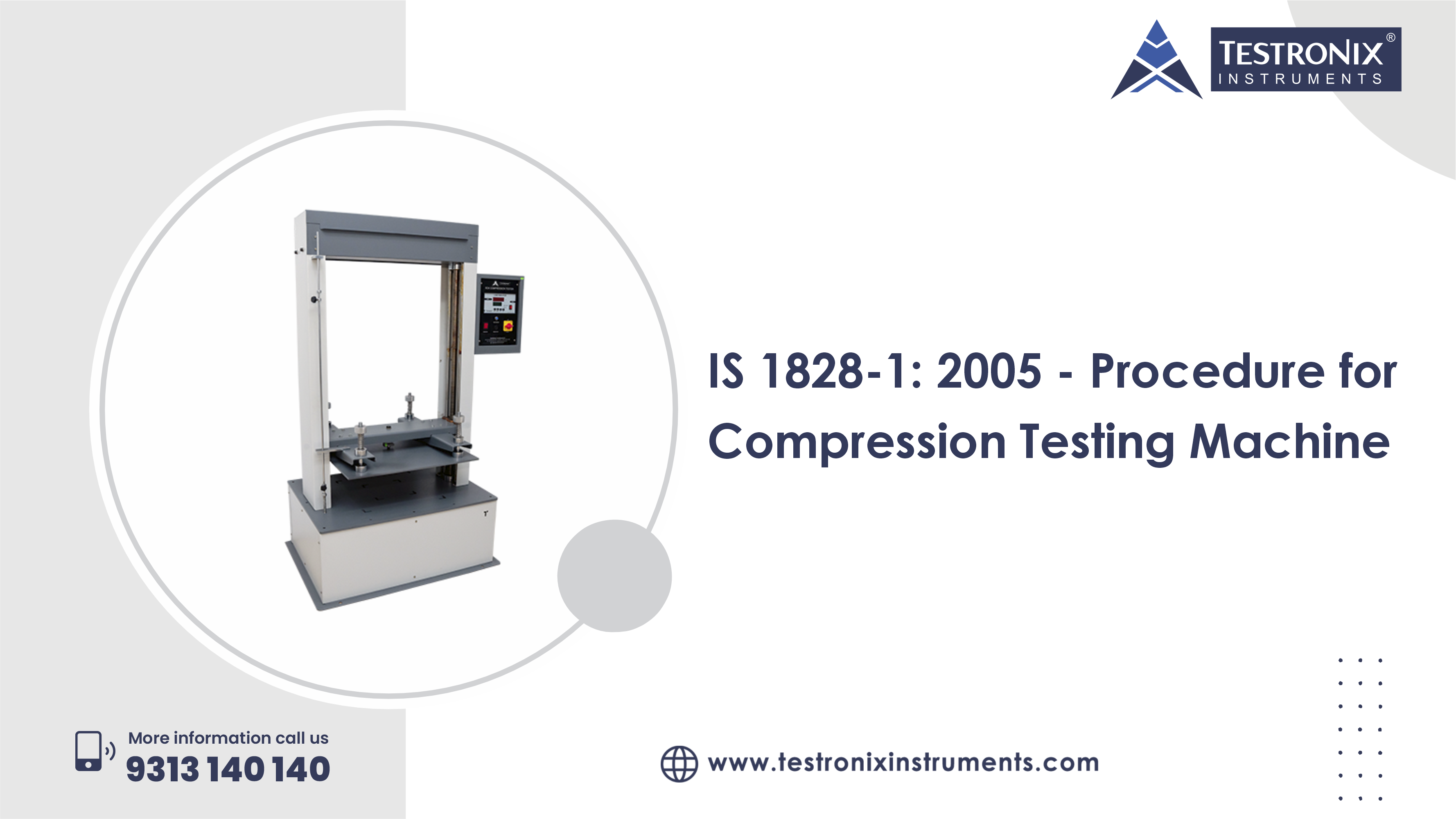
Testronix Box Compression Testing Machine: Compatible with IS 1828-1:2005
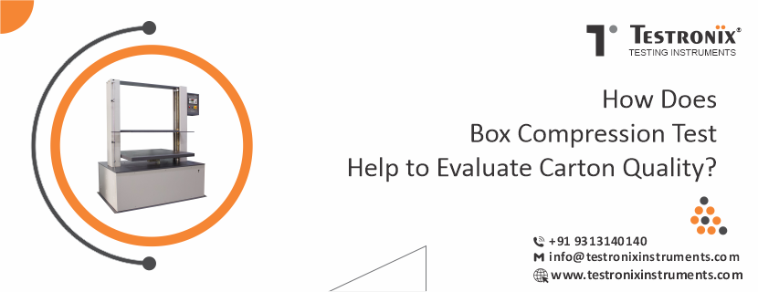
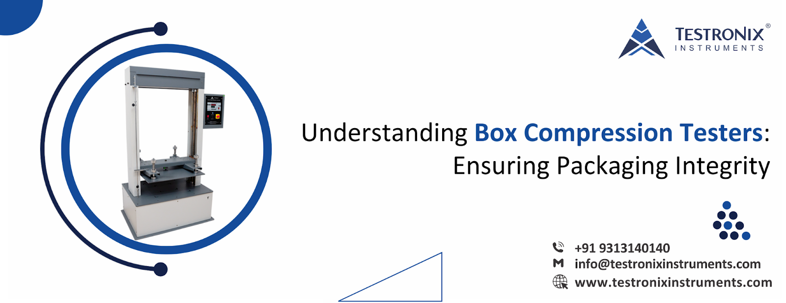
The Testronix box compression testing machine is built to comply fully with IS 1828-1:2005 calibration guidelines that deliver high-accuracy crush strength data for corrugated packaging. Its heavy steel frame keeps load readings stable across repeated laboratory testing cycles.
Building a compression frame that retains calibration over years of daily heavy use requires solid engineering. Testronix builds these units with high-grade load sensors and heavy platens engineered to prevent bending or frame twisting during peak load moments.
Digital controls make standard verification quick and straightforward. Its digital readout, peak load memory, and microprocessor controls match IS 1828-1:2005 Class 1 requirements easily, taking the stress out of annual lab audits for quality managers.
Conclusion
Calibration and verification of testing procedures and results are the most critical aspects to be followed in the manufacturing industry. To ensure that your packing compression data is accurate, consistent and repeatable, it is best practice to follow the usual calibration protocol as laid out in the IS 1828-1:2005 standard. Without routine calibration checks, even the best testing equipment can fail. Following the right calibration method ensures your reputation for quality and prevents fragile goods from being shipped to customers.
If you are looking to improve the performance of your quality laboratory by using accurate and standard-compliant testing devices, please contact Testronix Instruments.