Electronic and printed circuit boards (PCBs) tend to fail as standard visual inspection cannot detect hidden physical, chemical and electrical flaws. This is where standardized testing methods under IPC-TM-650 come into play, revealing ionic contamination, trapped moisture, thermal shock, trapped humidity, and other characteristics of an electronic product.
Typically, the IPC-TM-650 test is divided into two parts: Method 2.4.9 for solder float, or Method 2.6.7.2 for thermal shock. But in this article, we will cover the broader purpose of the IPC-TM-650 testing method, its detailed guide and scope, along with how to implement this test.
What is IPC-TM-650?
IPC-TM-650 Test Methods Manual is the global standard for testing printed circuit boards (PCBs) and electronic assemblies. Maintained by the Association Connecting Electronics Industries (IPC), it contains hundreds of standardized guidelines covering the physical, electrical, chemical, and environmental testing of electronics.
The term “IPC” stands for Association Connecting Electronics Industries, and “TM” stands for Test Method in IPC-TM-650. Manufacturers worldwide use the IPC-TM-650 manual and protocols to prove that their raw materials and finished circuit boards are reliable, durable, and ready for the market. It is a constantly updated library of specific, step-by-step test instructions developed by industry experts over decades. When a laminate supplier claims their resin can handle high temperatures or a board shop says their copper foil bonding meets industrial standards, they are referencing test procedures defined right inside this manual.
The following are the testing categories in which the IPC-TM-650 manual is divided:
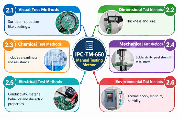 2.1 Visual Test Methods (Surface inspection like coatings)
2.2 Dimensional Test Methods (Thickness and size)
2.3 Chemical Test Methods (Includes cleanliness and resistance)
2.4 Mechanical Test Methods (Solderability, peel strength test, stress)
2.5 Electrical Test Methods (Conductivity, material behavior and dielectric properties)
2.6 Environmental Test Methods (Thermal shock, moisture, humidity)
Purpose and Scope of IPC-TM-650 For Electronics & PCB Testing
The core purpose of IPC-TM-650 is to provide a uniform baseline for verifying board reliability across six distinct technical categories before products reach end users.
The scope of IPC-TM-650 spans every physical aspect of circuit board fabrication and assembly. Electronics are exposed to demanding conditions, as seen in the presence of vibrations in engine bays of automobiles or freezing and thawing in air equipment operations. By means of test sequences, engineers can ascertain if the materials are resistant to these demanding conditions before starting full-scale manufacturing.
Six sections make up the lab manual and inner chapters deal with a certain physical property.
-
Section 1.0 Visual Test Methods: Optical inspection protocols for surface defects, base material inclusions, and physical dimensions.
-
Section 2.0 Dimensional Test Methods: Procedures for measuring hole locations, board thickness, warping, twist, and trace widths.
-
Section 3.0 Chemical Test Methods: Chemical analysis techniques to check solderability, ionic cleanliness, and resistance to flux residues.
-
Section 4.0 Mechanical Test Methods: Physical stress testing including peel strength, flexural endurance, tensile strength, and bond integrity.
-
Section 5.0 Electrical Test Methods: Dielectric breakdown, surface insulation resistance, impedance testing, and capacitance measurements.
-
Section 6.0 Environmental Test Methods: Thermal shock, humidity aging, thermal cycling, and fungus exposure evaluation.
IPC-TM-650 PDF Download
Access complete technical documentation and official IPC-TM-650 PDF test procedure downloads directly through the official IPC standards portal.
IPC-TM-650 PDF is a very helpful guide for quality assurance managers to maintain exact specifications, fixture setups, and tolerance calculations for individual test methods. You can obtain the complete manual or individual IPC-TM-650 test method PDF documents directly from the official IPC standards.
IPC-TM-650 - Method Manual of Electronics & PCBs
The IPC-TM-650 Method Manual structures hundreds of individual test procedures using a clear, numbered system designed for simple navigation in quality control laboratories.
Working with the manual requires understanding how individual methods are structured. Each procedure gets a specific decimal index. For example, Method 2.4.9 covers peel strength of flexible printed wiring, while Method 2.4.8 covers copper foil peel strength for rigid laminates. The first number is a direct reference to the main category of the section, which allows technicians to quickly find the right guidelines.
Every individual test method inside the manual follows a consistent standard layout:
|
Document Section |
What It Specifies |
|
Scope |
Defines the material or assembly type being evaluated and specific objectives of the test. |
|
Applicable Documents |
Lists cross-referenced IPC specifications, ASTM standards, or military norms. |
|
Test Specimens |
Details precise specimen dimensions, cut directions, and required surface preparation. |
|
Apparatus & Equipment |
Specifies test machines, load sensors, fixtures, and calibration tolerances needed. |
|
Procedure |
Step-by-step instructions for environmental conditioning, feed rates, and measurements. |
|
Calculations & Reporting |
Provides mathematical formulas for final values and documentation formats. |
IPC-TM-650 Testing Procedure
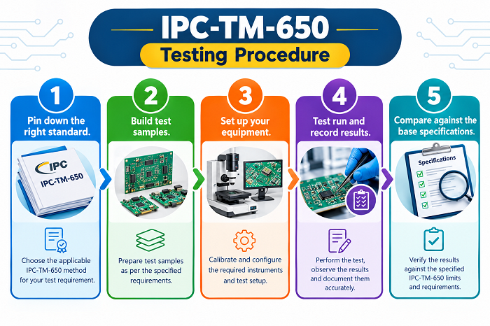
The following are the steps to perform tests under the IPC-TM-650 method manual:
-
Pin down the right standard. Figure out exactly which test spec applies to your project like heat resistance, stress testing, or whatever the requirement calls for.
-
Build test samples. Alongside your main circuit boards, add a few small sample strips (test coupons) specifically meant for destructive or evaluative testing.
-
Set up your equipment. Calibrate your lab gear, dial in the right temperature, and match the environmental conditions to whatever the standard specifies.
-
Test run and record results. Pass the coupons through the physical or thermal tests and take the actual data including weight change, resistance shift, and whatever the metric is.
-
Compare against the base specifications. See if your board passes the standards by comparing the measured values against the pass/fail limits.
This clear structure ensures testing remains repeatable. If a board laminate passes IPC-TM-650 Method 2.4.8 in a lab today, another engineer can rerun the exact setup next month and confirm those results with total confidence.
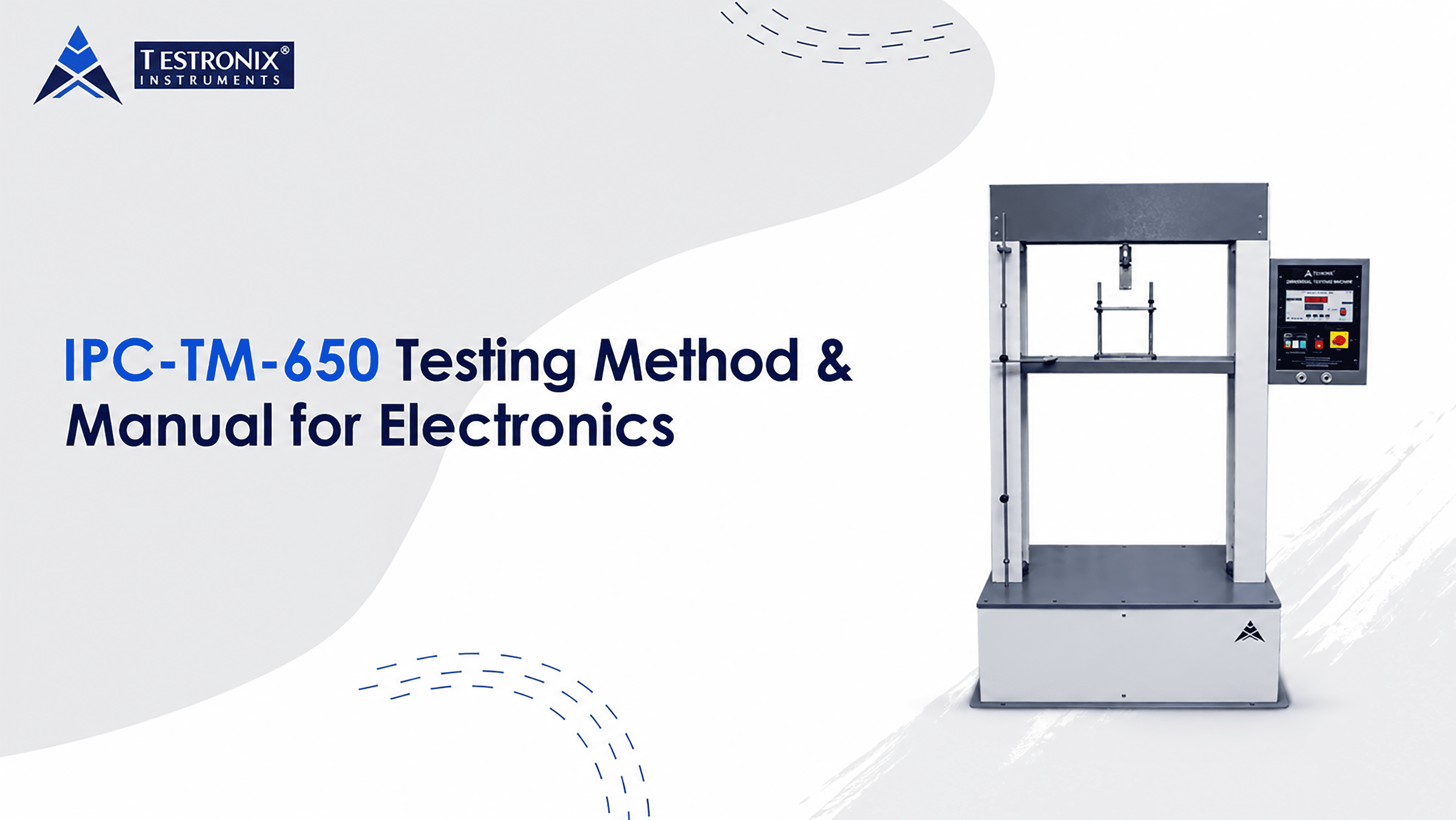
Testronix Peel Strength Tester for PCB Manufacturing Under IPC-TM-650
Testronix Peel Strength Tester provides precise motorized force measurement specifically designed to execute IPC-TM-650 Method 2.4.8 for evaluating copper foil adhesion on circuit boards.
Mechanical adhesion between copper foil and base dielectric material is one of the most critical factors in PCB survival. If copper bond strength is weak, traces lift away during soldering, rework, or field operation. IPC-TM-650 Method 2.4.8 defines exact mechanical tests to measure copper bond strength under vertical load. Doing this test properly requires dedicated hardware designed to maintain constant pull speeds and eliminate hand-driven movement variations.
This part is important when selecting laboratory equipment. The Testronix Peel Strength Tester is designed to accommodate all these mechanical requirements. It is equipped with a high precision motor drive that removes conductive copper foil from laminate samples at standard controlled speeds and angles. In terms of copper bond strength, digital sensors give technicians a precise measurement of peak force and ongoing load, with no human error thrown into the equation.
Put simply, the IPC-specific equipment ensures quality control is maintained throughout production runs. Facilities running the Testronix Peel Strength Tester can quickly verify raw laminate stock before sending boards through expensive etching, plating, and surface mount assembly lines. Catching weak copper foil bonding early saves thousands in wasted materials and prevents product field failures.
Conclusion
The implementation of IPC-TM-650 testing processes is an essential part of assuring the quality of a product, reducing the probability of costly circuit failures, and ensuring physical performance of components.
Reliable electronics assumes a detailed physical validation of the product rather than chance and just a simple visual inspection. IPC-TM-650 enables PCB manufacturers to comply with technical standards for testing the tensile strength of PCB laminate and mechanical adhesion as well as the dielectric properties of laminate.
Upgrade Your PCB Quality Testing with Testronix Instruments
For every electronic firm and organization, it is important that printed circuit boards (PCBs) meet strict IPC-TM-650 standards demands dependable, accurate laboratory equipment. Testronix Instruments offers the most advanced testing instruments such as the top-notch Peel Strength Testers that will make the testing process smoother.
Reach out to the expert team at Testronix Instruments today to request a quote, schedule a live product demonstration, or find the ideal testing machinery for your manufacturing line.