For quality assurance testing for electrical and electronics, passive components must be measured accurately and this can be done with an LCR meter. An LCR meter measures reactance, impedance, and ohmic resistance (R). LCR meters are typically applied to laboratory tests and assessments, but also manufacturing, repair service and warranty work are often performed using LCR meters. Passive components are usually tested using the LCR meter under various operating conditions.
What is an LCR Meter?
An LCR meter is an electronic test instrument that measures the capability (L), capacitance (C), and resistance (R) of electronic devices, sensors or components. In addition to measuring these values, it can also measure other parameters related to quality such as dissipation factor, voltage, current, phase angle, conductance, and susceptance.
LCR Meter Full Form
LCR meter full form stands for Inductance (L), Capacitance (C) and Resistance (R) to measure electronic components accurately at various frequencies.
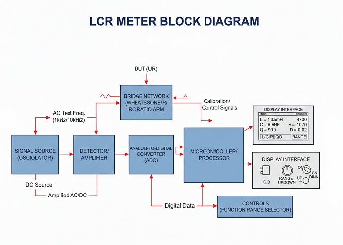
LCR Meter Block Diagram
The block diagram of an LCR meter describes several essential components discussed below:
-
Signal Source (Oscillator): Responsible for producing the AC test frequency that is to be used for L/C measurements (such as 1 kHz or 10 kHz). In the case of resistance testing, a DC source is generally used.
-
Bridge Network (Wheatstone/RC ratio Arm): Wheatstone Bridge or RC Ratio Bridge networks are used to compare the device under test (DUT) to standard components (such as resistors (R), inductors (L), and capacitors (C).
-
Detector/Amplifier: Amplifies the low-level (but may have a phase shift) AC voltage generated by the bridge circuit which helps achieve a more accurate measured result.
-
Analog-to-Digital Converter (ADC): Converts the DC voltage or current output of the Detecting-Amplifying Unit into a digital format that can be common to other devices used for recording or processing information.
-
Microcontroller/processor: The digital data processing, calculations like impedance, Q-factor, phase angle and measurement calibration are managed by the microcontroller or processor.
-
Display Interface: The display shows the calculated values of inductance (L), capacitance (C) or resistance (R), often allowing the user to select different measurement ranges and types (L, C, R, Q, D).
-
Controls (Function/Range selector): knobs or buttons to select L, C, or R measurement mode and set proper and correct ranges of measurement.
Working Principle of LCR Meter
The operating principle of an LCR meter is based on measuring the impedance of the device component. It does this using an alternating current (AC) test signal applied to the component under test and measuring the voltages & currents generated by the test signal.
The resistive (R) component of impedance can be obtained by measuring and comparing the magnitude of the in-phase elements of the currents against the test signal, and the reactive impedance element may be used to obtain the inductance (L) and capacitance (C) values of the element under test.
How to Use LCR Meter- Step-wise Guide
Preparing equipment and workspace, calibrating the LCR meter, selecting measurement mode and frequency, connecting components to the LCR meter, and taking measurements and analyzing results are all included in the LCR meter process. All of these tasks have many subtasks as well as some troubleshooting possibilities.
-
Equipment Preparation
The LCR meter utilized must have sufficient current for measurements, proper functioning and be unaffected by any external sources of electrical interference during measurements with other electrical/electronic items or metals in the surrounding.
-
Calibrate the LCR Meter
You must perform either open, short, or load calibration as necessary. Calibration compensates for measurement errors that occur due to test lead and internal circuit resistance. By calibrating your instruments, you can obtain a reliable reading with good accuracy, especially on units that have very small resistance.
-
Select the Measurement Mode and Frequency
After determining which component to measure (inductor, capacitor, or resistor), choose a frequency for testing that matches the component's behavior since component impedance and phase are frequency dependent. Selecting the correct frequency results in accurate impedance analysis and accurate phase detection for accurate LCR readings.
-
Connect the Component to the LCR Meter
When you attach the component to either the test terminals or the test fixture, make sure the connection is secure. Make sure to observe the correct polarity for polarized components and also provide proper fitment and tight connections to eliminate any noise or errors.
-
Take and Analyze Measurements
Connect the parts to the AC Test Excitation and watch how the display reacts to the measurements for resistance, capacitance, or inductance, as well as the Q-factor or losses if needed. Then, compare these measurements to the manufacturer's specifications to see how well the components compare to the manufacturer's specifications to assess how closely components match their stated specifications.
-
Record and Troubleshoot
The documentation of recorded results from your measurements includes both reference materials and reportable data. The process of correcting a problem with your measurement results is to begin by confirming the connections and recalibrating the instrument or replacing any defective components. Once you have corrected the problems associated with your measurement system, you can have accurate and reliable results and reduce the potential for getting the same error repeatedly.
Applications of LCR Meter
LCR Meter comprises several applications such as testing inductors, capacitors, and resistors; quality control in electronics manufacturing; research and development laboratories; fault detection in electronic circuits; and incoming inspection of electronic components.
Here are the applications described below:
-
Measure LCR, Inductance, Capacitance, and Resistance.
LCR meters help measure and identify inductor, capacitor, and resistor values to ensure their accordance with manufacturer specifications so that engineers/technicians may use them in the construction and/or the maintenance of circuits.
-
Quality Control in Electronics Manufacturing
LCR meters are used in manufacturing and providing quality control to determine whether components meet tolerance and performance standards. By measuring the exact values of inductors, capacitors, and resistors, defective parts cannot enter assemblies. Consistent product quality, longevity, and reliability are ensured for consumer electronics, industrial equipment, and telecommunications equipment.
-
Research and Development Laboratories
R&D engineers utilize LCR meters when testing/creating their new component designs. They use the data and the frequency dependency of their circuit to optimize its performance. R&D utilizes the data gathered via LCR meters in the design and development of efficient and high-performance electronic systems, and through it can choose appropriate components for their innovative designs.
-
Fault Detection in Electronics Circuit
Identification of damaged components in a functional circuit via an LCR meter is made simple by comparing measured values with the manufacturer's specifications to determine the differences between the two values. By identifying resistors, capacitors, or inductors affected by degradation, shorts, or opens, technicians are able to troubleshoot quickly and repair devices.
-
Incoming Inspection of Electronics Components
Before the assembly process, vendors evaluate their incoming components using LCR meters to confirm that these products meet defined specifications (for all components). This process ensures that only compliant capacitors, resistors, and inductors are used in assembly. Lowering the chance of mistakes in assembly increases production yield while simultaneously improving reliability across complete product lines.
What is the difference between an LCR meter and a multimeter?
LCR Meter vs Multimeter:
|
Feature |
LCR Meter |
Multimeter |
|
Primary Function |
Measures L, C, and R accurately |
Measures voltage, current, and resistance |
|
Measurement Signal |
Uses an AC signal |
Mostly DC (basic AC in some cases) |
|
Accuracy |
High precision |
Moderate |
|
Frequency Selection |
Yes |
No |
|
Measures Inductance & Capacitance |
Yes |
Limited or not available |
|
Application |
Component analysis and QC |
General electrical testing |
Conclusion
The LCR meter is a critical device for accurately testing and analyzing all types of passive components in electronic circuits. It allows the user to determine the inductance, capacitance, resistance, and impedance of components at multiple frequency levels.
The LCR meter is an important tool for both electronics manufacturing and electronics research/engineering.